As demand for electrification grows across automotive and marine sectors, overmoulding copper busbars has become a critical process in developing reliable power distribution components.
At Dudley Associates, we specialise in busbar overmoulding in the UK, supporting customers through prototype injection moulding and low-to-medium volume production. These projects often sit within new product development (NPD), where flexibility and technical understanding are essential.
What is Overmoulding for Copper Busbars?
Overmoulding is a form of injection moulding copper inserts, where a polymer is moulded around a pre-formed metal component—in this case, copper busbars.
This process:
- Electrically insulates conductive elements
- Protects against environmental factors
- Enables integration into complex assemblies
In many cases, these overmoulded components are produced using high-performance polymers such as:
- PPS
- LCP
- PEEK
These materials are commonly specified for automotive powertrain components and marine electrical systems, where thermal stability, chemical resistance, and electrical insulation are critical.
Tooling Strategy: Aluminium vs P20 Steel
A key decision in any prototype tooling project is whether to modify an existing tool or manufacture a new one —balancing technical requirements alongside an awareness of CAPEX constraints, particularly at the development stage.
For most low volume injection moulding applications, aluminium tooling offers:
- Faster lead times
- Cost efficiency
- Flexibility for design iterations
However, material selection can change this approach.
When processing high-performance polymers such as PEEK, P20 steel mould tools are required. These materials operate at very high processing temperatures, meaning aluminium tools are not suitable for sustained or repeatable production.
Why Busbars Overmoulding Isn’t Fully Automated
Unlike high-volume manufacturing, manual insert moulding is often necessary for prototype and development work.
Each cycle typically involves:
- Hand-loading copper inserts into the tool
- Precise positioning to ensure correct encapsulation
- Visual checks before injection
This is especially important in copper insert moulding, where even minor variation in insert geometry can affect the final part.
In some cases, inserts may arrive slightly out of specification—something that must be managed carefully within the moulding process.
Challenges in Prototype Injection Moulding
One of the most common misconceptions around prototype injection moulding UK is the expectation of production-level efficiency.
In reality, achieving optimal processing conditions takes time—particularly when working with high-performance polymers like PPS, LCP, and PEEK, which demand precise thermal control.
Factors such as:
- Material temperature
- Tool temperature
- Flow characteristics
must stabilise before consistent parts can be produced.
It’s not unusual for multiple sets of inserts—sometimes four or more—to be used during setup alone.
Understanding Scrap Rates in NPD Projects
Because these are short-run, low volume injection moulding projects, scrap rates are naturally higher.
This is influenced by:
- Process stabilisation during setup
- Manual handling of inserts
- Material sensitivity (especially with high-performance polymers)
- Ongoing design validation
For businesses unfamiliar with plastics manufacturing, this can initially seem inefficient. However, in NPD environments, this is a necessary part of refining both the component and the process.
Better Outcomes Through Collaboration
To bridge this gap, we often work closely with customers to improve understanding of the insert moulding process for electrical components.
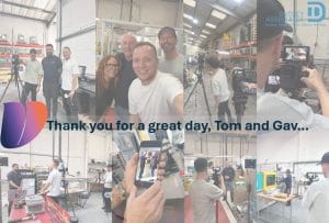
In one recent project, inviting the customer onsite—whose expertise lies in metal rather than plastics—provided valuable insight into:
- The realities of manual insert moulding
- Why automation isn’t always viable
- The impact of high-performance materials on processing conditions
- The factors affecting yield in prototype runs
This collaborative approach led to better alignment, reduced pressure on unrealistic yield expectations, and ultimately a stronger working relationship.
That shared understanding is important to us. We take pride not only in the components we produce, but in helping our customers build confidence in the process behind them.

Supporting Powertrain Innovation
As electrification accelerates, the demand for reliable overmoulded busbars for powertrains continues to grow—particularly those manufactured using advanced materials such as PPS, LCP, and PEEK.
Delivering these components isn’t simply a matter of processing capability. It requires a clear understanding of how material behaviour, tooling strategy, and development-stage constraints interact—especially within low-volume, prototype environments.
In our experience, successful outcomes are shaped by:
- Selecting tooling approaches that reflect both technical demands and CAPEX sensitivity
- Understanding the processing nuances of high-performance polymers
- Recognising the limitations of manual insert moulding in early-stage production
- Maintaining open, informed dialogue around yield, scrap, and process stability
Ultimately, progress in EV and marine powertrain development depends on more than just the final component. It relies on shared understanding—between customer and manufacturer—of what it takes to move from concept to a stable, repeatable process.