What design engineers need to know before finalising the CAD
A plastic component can look completely finished on screen and still be difficult, expensive or unreliable to manufacture. That is one of the biggest differences between designing a product and designing a product specifically for injection moulding.
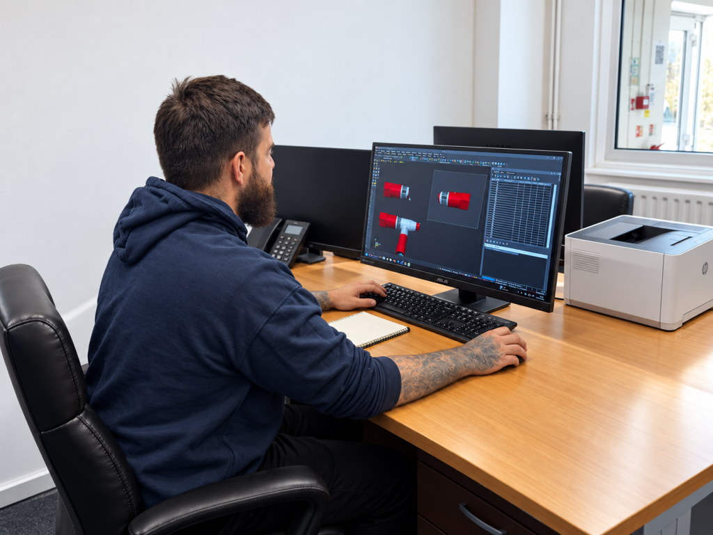
The CAD model might perform exactly as intended. The dimensions may work, the component may fit correctly into the wider assembly and everything may look right. But once that design has to become a mould tool, another set of questions starts to appear.
Can the plastic flow into every area of the cavity properly? Will the component cool evenly? Can it be removed cleanly from the mould? Are there thick sections that could lead to sink marks or distortion? Are there undercuts that will require additional tooling mechanisms? Are the tolerances realistic for a moulded plastic component?
Could relatively small changes now make the component easier, faster and less expensive to manufacture later?
At Dudley Associates, this is one of the main reasons we encourage product designers and design engineers to involve the moulding and toolmaking team before the design is completely finalised. It does not mean handing over control of the design. You understand what the product needs to do. We can help make sure it is also designed around how it will actually be tooled, moulded, inspected and produced.
Start with the whole manufacturing picture
Good design for injection moulding is rarely about one isolated feature. Wall thickness, ribs, bosses, draft, undercuts, gating, ejection, material, tolerances and surface finish all influence one another.
A design change that makes the product stronger could also make it harder to cool. A feature added for assembly may create an undercut. A cosmetic requirement may influence where the tool can split or where the gate can be placed. A material change may affect shrinkage, tooling wear or dimensional stability.
That is why Dudley Associates prefers to look at the component, material, mould tool and production process together rather than treating them as separate stages.
Wall thickness, ribs and bosses
Wall thickness is one of the first things an injection moulding engineer will look at, and one of the main considerations is consistency. When molten plastic enters the mould it starts cooling almost immediately, so areas of very different thickness can cool and shrink at different rates.
That can contribute to sink marks, warpage, internal stresses, dimensional variation and longer cycle times. It also means using more material than may actually be necessary.
This does not mean every part has to have perfectly uniform walls, but it does mean sudden changes in thickness should be considered carefully. In some cases, a component can be made stiffer through better geometry rather than simply adding more plastic.
Ribs are a good example. They can add useful rigidity without making the entire component thicker, but they still need to be proportioned correctly. A rib that is too heavy in relation to the surrounding wall can create a visible sink mark on the opposite surface.
Bosses need similar thought. They are common on moulded components because they are useful for screws, fixings and locating features, but large solid bosses can create local concentrations of material. These thicker areas can cool differently and may lead to sink, distortion or stress.
At Dudley Associates, we would normally look at the wall sections, ribs, bosses and material together. Sometimes a small change to the geometry can improve both the moulding process and the finished part without changing the basic function of the design.
Draft, radii and getting the part out of the mould
Once the plastic has cooled, the component still has to come out of the mould. That sounds simple, but plastic tends to shrink onto cores and other internal features as it cools, so parts can grip the tooling surprisingly tightly.
This is where draft angles become important. A slight taper on surfaces that run in the mould-opening direction helps the component release cleanly rather than dragging against the tool. The amount of draft needed depends on the material, depth of the feature, surface texture and overall geometry.
Surface texture can make draft even more important because the moulding needs to release from the textured steel without being marked or damaged. It is much easier to build draft into the CAD at the design stage than to discover later that the component is difficult to eject.
Radii matter for similar reasons. Sharp internal corners can create stress concentrations in the plastic, affect flow and make the mould more difficult to manufacture. Sometimes a sharp feature is genuinely required, and technologies such as EDM can help produce complex details in the tool, but if a sharp corner does not serve a real functional purpose, a sensible radius can often improve both the product and the tooling.
Ejection itself also needs planning. Ejector pins or other mechanisms have to apply enough force to release the component without damaging or marking it, so their position can matter just as much as the amount of force used.
When everything has been designed properly, the process looks easy. The mould opens, the part comes out and the next cycle begins. Quite a lot of engineering can sit behind making it look that straightforward.
Undercuts and unnecessary tooling complexity
An undercut is a feature that prevents a component from being removed directly from the mould in the normal opening direction. Side holes, hooks, clips and certain internal features can all create undercuts.
These features are mouldable, but they may require slides, lifters, side actions, collapsible cores or other moving tooling components. That adds complexity to the mould and can also increase machining time, maintenance requirements and sometimes cycle time.
That does not mean undercuts should always be removed. Some are essential to the function of the product. But it is worth asking whether they are necessary before automatically designing a more complicated tool around them.
This is one of the areas where early discussion can save cost. A small change to a feature while it is still in CAD may remove the need for a much more expensive tooling mechanism later.
Parting lines, gates and how the mould fills
Most injection mould tools have two main halves, and where those halves meet creates the parting line. That line has to appear somewhere on the component, so its position needs to be considered in relation to appearance, function, tooling and ejection.
On a hidden industrial component it may not matter much at all. On a visible consumer product, it can be far more important.
The gate needs similar thought. This is the point where molten plastic enters the mould cavity, and although it may be a relatively small feature, its position can influence how the cavity fills, where weld lines form, how the part packs, how it shrinks and where any gate witness appears on the finished moulding.
It is easy to think the gate should simply be put in the least visible place, but the plastic still needs to fill the component properly. Sometimes appearance and moulding requirements align perfectly. Sometimes a compromise is needed.
For multi-cavity tooling, flow balance between cavities becomes another consideration, particularly where consistent part quality is important over long production runs.
Tolerances and dimensional accuracy
Injection moulded parts can be manufactured very accurately, but plastic does not behave in the same way as machined metal. The finished dimensions can be influenced by material shrinkage, mould temperature, processing conditions, component geometry, moisture absorption, fibre reinforcement and cooling.
This means tighter tolerances usually require more care in tooling, processing and inspection. That does not mean they should be avoided where they are genuinely required, but putting very tight tolerances on every dimension can create unnecessary cost and difficulty.
Which dimensions actually matter to the function of the product?
Those are the dimensions that deserve the greatest attention. At Dudley Associates, CMM inspection can be used to verify critical dimensions and monitor production, but dimensional control starts much earlier than the inspection stage. It starts with sensible tolerancing, appropriate material selection and a stable moulding process.
Sink marks and warpage
Sink marks and warpage are two of the problems designers often want to avoid, but both can start with decisions made in the CAD model.
Sink marks commonly occur where there is a thicker concentration of material beneath the visible surface. Bosses, ribs and heavy sections are typical examples. As the inside of that thicker section continues cooling and shrinking, it can pull the outer surface inwards and leave a visible depression.
Warpage happens when different areas of the component shrink or cool differently, causing the part to distort. Uneven wall thickness, material behaviour, fibre orientation, cooling, gate position and processing conditions can all contribute.
Good process development can help manage both issues, but part geometry is a major starting point. That is why Dudley Associates likes to review the design and material together before tooling begins, rather than trying to solve everything later through processing alone.
Surface finish and appearance
The surface finish of the final component is largely created by the mould itself, so cosmetic requirements should be considered before the tool is manufactured.
A highly polished cavity can create a smooth glossy surface, while other areas may deliberately be textured. These choices can influence tool polishing, draft requirements, mould release and the visibility of flow lines, weld lines or other minor imperfections.
For a hidden technical component, appearance may be relatively low on the priority list. For a visible housing or customer-facing product, it may be very important.
The key is making those requirements clear early enough for them to be incorporated into the tool design rather than treated as an afterthought.
How design affects tooling cost
Two plastic components of similar size can require completely different mould tools.
Features such as multiple undercuts, side actions, complex internal geometry, demanding surface finishes, tight tolerances, difficult ejection and complicated cooling can all increase tooling complexity.
Production volume matters too. A mould expected to produce a short test batch does not necessarily need to be engineered in the same way as one expected to manufacture millions of components over many years.
This is why Dudley Associates considers tooling cost in the context of the complete manufacturing requirement. The cheapest tool is not always the cheapest way to produce the component, but there is equally little benefit in over-engineering a tool for a genuinely low-volume application.
The right tooling strategy is the one that suits the product, material, volume and expected production life.
How design affects cycle time and component cost
For high-volume production, cycle time can have a major effect on the eventual component cost.
Wall thickness is one obvious influence because thicker sections generally need longer to cool. Material, cooling design, ejection and component geometry can all have an effect as well.
On a run of a few thousand parts, several additional seconds may not dramatically change the economics. Across hundreds of thousands or millions of cycles, those seconds can add up to a considerable amount of machine time.
That does not mean the answer is simply to run the mould as fast as possible. A good production process needs enough margin to remain stable, protect the tool and produce consistent parts.
At Dudley Associates, the aim is to find the right balance between speed, quality, repeatability and tool life rather than chasing the shortest possible cycle at any cost.
Material and product design should develop together
Material selection should ideally happen alongside product design rather than being treated as a completely separate decision.
Different polymers have different flow characteristics, shrinkage rates, mechanical properties, temperature resistance, chemical resistance and moisture behaviour. Some reinforced materials provide greater stiffness but may also introduce different shrinkage patterns, fibre orientation or tooling wear.
That means a geometry that works very well in one polymer may need changing if another material is chosen.
Equally, a design change may allow a less expensive material to perform perfectly well where a higher-specification polymer would otherwise have been needed.
This is why Dudley Associates encourages customers to discuss material, product design and tooling together wherever possible.
When should the moulding company get involved?
Ideally, before the design is completely finished.
That does not mean the moulding company needs to design the product for you. The product designer remains responsible for what the product needs to do and how it should function.
The moulding and toolmaking team can bring another perspective. We can look at whether the selected material is appropriate, whether the walls are sensible for moulding, whether the part can be released cleanly, where the tool might split, how it might be gated, whether undercuts are essential, how it will be ejected and what tooling approach makes sense for the expected production volume.
At Dudley Associates, these conversations can happen while changes are still relatively straightforward to make.
That matters because changing a CAD model is usually much easier than changing a completed mould tool.
A practical design for injection moulding checklist
Before releasing a plastic component for tooling, it is worth checking the following:
- Is the material suitable for the actual operating environment?
- Are wall thicknesses reasonably consistent?
- Could ribs or geometry provide stiffness instead of extra material?
- Are bosses designed with moulding in mind?
- Is there enough draft for reliable ejection?
- Are sharp corners genuinely necessary?
- Does the component contain undercuts?
- Could any undercuts be removed through a design change?
- Has the likely parting line been considered?
- Where could the component be gated?
- How will the component be ejected?
- Which dimensions genuinely require tight tolerances?
- Are cosmetic surfaces clearly identified?
- Could thick sections lead to sink marks?
- Is the geometry likely to encourage warpage?
- Does the tooling approach suit the expected production volume?
- Could the design be simplified to reduce tooling complexity?
- Has cycle time been considered as part of component cost?
- Will secondary operations or assembly be required?
- Has the injection moulding and toolmaking team reviewed the design before it is finalised?
You do not necessarily need to answer all of those questions yourself. That is the value of involving the manufacturing team while there is still time to act on the answers.
Good design for injection moulding is about balancing priorities
There is rarely a perfect component design with absolutely no compromises.
A design engineer may want the thinnest possible product. The toolmaker needs enough room to manufacture the mould reliably. The injection moulder wants the component to fill, cool and eject consistently. The customer needs the product to perform properly and hit its cost target.
All of those requirements need to come together.
That is why design for manufacture should not be viewed simply as somebody checking the CAD once everything else is finished. At its best, it is an ongoing conversation between the people who understand the product and the people who understand how it will be manufactured.
Dudley Associates can get involved before the mould tool is commissioned
One of the most expensive times to discover a design problem is after the tool has already been made.
Early involvement allows Dudley Associates to consider the complete manufacturing process while changes are still relatively easy to make. That can include product design and development input, material selection, design for manufacture, mould tool design and manufacture, tool trials, injection moulding, CMM inspection, cleanroom production, secondary operations and assembly.
Whether the project is a prototype, a short production run or a component that may eventually be produced in its millions, the principle is the same.
The goal is not simply to design a part that can be injection moulded. It is to design a part that can be moulded reliably, consistently and economically throughout its production life.
Frequently Asked Questions
What is design for manufacture in injection moulding?
Design for manufacture, often shortened to DFM, is the process of reviewing a component to make sure it can be produced reliably and economically. For injection moulded parts, that includes areas such as wall thickness, draft, ribs, bosses, undercuts, tolerances, material selection, gating, ejection and tooling complexity.
When should DFM be carried out?
Ideally, before the product design is finalised and before the mould tool is commissioned. Changes made in CAD are generally easier and less expensive than modifications to completed tooling.
What is the most important rule when designing an injection moulded part?
There is no single rule, but consistent wall thickness, sensible material selection, adequate draft and consideration of how the component will fill, cool and eject are all important.
Can undercuts be injection moulded?
Yes. Undercuts can be produced using slides, lifters, collapsible cores and other tooling mechanisms, but they usually add complexity and cost to the mould.
Why should a product designer speak to a toolmaker before finishing the design?
A toolmaker can identify manufacturing considerations that may not be obvious from the CAD alone. Small changes made early can sometimes simplify the tooling, improve moulding stability, reduce cycle time or avoid expensive modifications later.
Can Dudley Associates review an existing product design for injection moulding?
Yes. Dudley Associates can work with customers during product development to review material selection, manufacturability, tooling requirements and the eventual injection moulding process before tooling is commissioned.