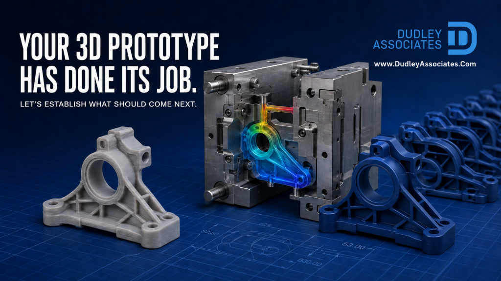
A 3D-printed prototype can prove that an idea works.
It can help you assess size, shape, fit, assembly, ergonomics and customer reaction without committing to production tooling.
But it does not necessarily prove that the same design can be injection moulded successfully.
A prototype proves that a shape can exist. It does not prove that molten polymer can fill, pack, cool and release from that shape repeatedly.
That distinction becomes important when the next questions are:
- Can we manufacture the component in its intended production material?
- Will it remain flat and dimensionally stable?
- Will clips, bosses, seals and fixing points perform under load?
- Can we produce repeatable batches?
- Will it withstand the real operating environment?
- How much tooling investment is sensible when future demand is still uncertain?
For many early-stage products, the answer is not to jump immediately into a fully hardened production tool. Aluminium or P20 steel tooling can provide a practical route between a 3D-printed prototype and repeatable production.
3D printing has done its job
3D printing is extremely valuable during product development. It allows engineers to test ideas quickly and identify obvious design problems before committing to metal.
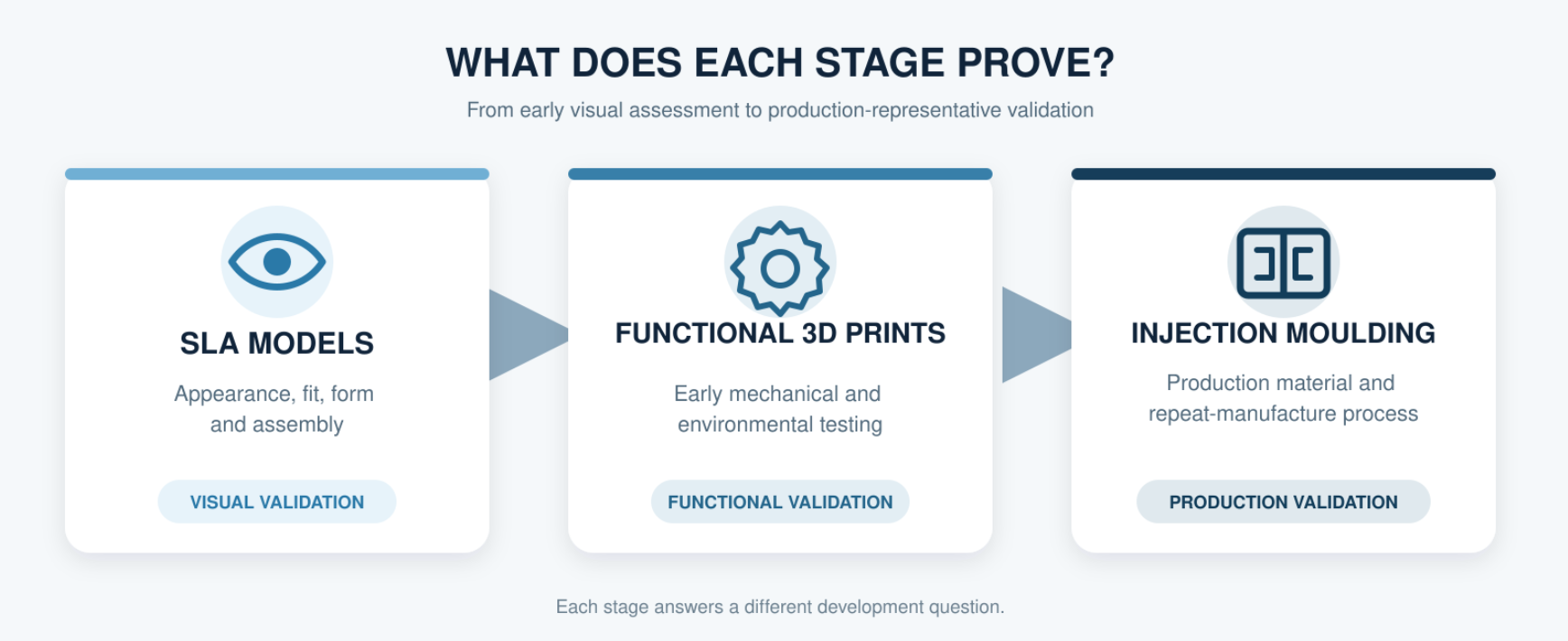
SLA models can provide particularly good surface detail and are useful for visual, ergonomic and assembly reviews. Other additive manufacturing processes can also produce functional end-use parts.
However, a printed component and an injection-moulded component are created through fundamentally different processes.
Injection moulding introduces:
- Molten polymer flowing through a gate and runner system
- Pressure during filling and packing
- Material shrinkage
- Different cooling rates across the component
- Residual stress
- Fibre orientation in filled materials
- Tool split lines and ejection requirements
- Restrictions relating to draft, undercuts and wall thickness
These factors can change the final dimensions, flatness, strength and appearance of the component.
A design that prints perfectly may therefore need modifying before it can be moulded reliably.
When is a 3D-printed part no longer enough?
There is no single answer based purely on quantity. The decision usually comes down to what the component must prove next.
Injection-moulded development parts should be considered when you need to validate:
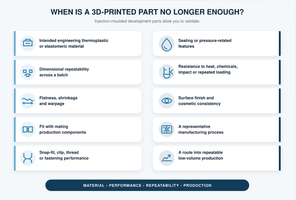
- The intended engineering thermoplastic or elastomeric material
- Dimensional repeatability across a batch
- Flatness, shrinkage or warpage
- Fit with mating production components
- Snap-fit, clip, thread or fastening performance
- Sealing or pressure-related features
- Resistance to heat, chemicals, impact or repeated loading
- Surface finish and cosmetic consistency
- A representative manufacturing process
- A route into repeatable low-volume production
This is particularly relevant in electronics, automotive, aerospace and defence, and medical applications, where material performance, traceability and manufacturing consistency may matter as much as the geometry.
3D-printed plastics can be suitable for demanding applications when the complete material and printing process have been properly qualified. However, material properties can be influenced by print orientation, build settings and post-processing. UL Solutions operates a dedicated certification programme for additive-manufacturing plastics because the printing process itself can affect material performance. UL Solutions explains this process-related variability here.
The question is not simply, “Is this resin suitable?”
It is:
Will this material, manufactured through this particular process, meet the actual product requirement?
What changes when a design moves towards injection moulding?
The original CAD model should be reviewed specifically for injection moulding before tooling begins.
A design for manufacture review may consider:
- Wall thickness and transitions
- Rib and boss proportions
- Draft angles
- Radii and sharp internal corners
- Split-line position
- Gate position
- Ejection strategy
- Undercuts and side actions
- Material shrinkage
- Sink, weld-line and air-trap risks
- Cooling and potential warpage
- Critical dimensions and tolerances
Some changes may be small. Others can affect the fundamental construction of the component.
This does not mean the 3D-printed design was wrong. It means it was created for one manufacturing process and is now being prepared for another.
What mould flow analysis tells us before metal is cut
At Dudley Associates, we use mould flow analysis with Moldex3D to examine how the nominated material is likely to behave inside the proposed component and tool.
Depending on the project, the analysis can help us assess:
- Filling behaviour
- Pressure requirements
- Gate location
- Weld-line formation
- Air traps
- Packing
- Cooling
- Shrinkage
- Residual stress
- Fibre orientation
- Potential warpage
Moldex3D describes these capabilities as a way to identify manufacturability risks and potential defects before production tooling is completed. Its flow-analysis software predicts issues including weld lines and air traps, while its warp analysis considers filling, packing, cooling and material behaviour when evaluating deformation. Further information is available from Moldex3D here.
Simulation is not a magic button, and it does not replace experienced tool design. It gives the project team better evidence on which to base design decisions.
That evidence is especially valuable when flatness, tight assembly, sealing or dimensional stability are critical.
A real example: the prototype worked, but the moulded design would not
In 2025, a customer approached Dudley Associates with a 3D-printed component.
The printed prototype had allowed the team to develop the concept, but they were concerned that the same geometry might not be suitable for injection moulding.
They were right to ask.
Our initial review and mould flow analysis indicated that the proposed filling behaviour, shrinkage and resulting stress were unlikely to produce the required flatness consistently.
The component might have looked correct in CAD, but the simulated moulding process told a different story.
Because the issue was identified early, our in-house design team could recommend changes before the tooling design was finalised. The customer could then continue towards injection moulding with a design better suited to the process and its required performance.
The 3D-printed prototype had proved the product concept.
The simulation helped prove whether the manufacturing concept would work.
That is precisely the point at which early technical feasibility can prevent expensive tool modifications later.
Why aluminium tooling is often the next logical step
When demand is still developing, committing immediately to a fully hardened steel tool may feel disproportionate.
Aluminium tooling can provide far more than a short-term development route. At Dudley Associates, we manufacture aluminium production tools for genuine low-to-medium-volume programmes, allowing components to be moulded in the nominated production thermoplastic or elastomer without automatically committing to fully hardened steel tooling.
With the right component design, material choice, processing conditions and maintenance, aluminium tooling can deliver a long and reliable production life. Some of the aluminium tools we manufacture with are more than 20 years old and remain in active service. We maintain and repair our customers’ tooling throughout its working life, helping to maximise the number of production shots achieved and extend the value of the original investment.
Aluminium tooling can be particularly useful for:
- Functional product testing
- Low-to-medium-volume manufacture
- Pilot production
- Customer or investor samples
- Market-launch quantities
- Design validation
- Material testing
- Bridge production while demand develops
- Components with an uncertain initial forecast
Tool life should not be judged by tool material alone. Component geometry, polymer type, filler content, production conditions and ongoing maintenance all influence how many reliable shots a tool can ultimately deliver.
 For an electronics product, that might mean testing an enclosure, connector body, sensor housing or insulating component in the intended polymer.
 In aerospace and defence, it could support the validation of a ruggedised housing, protective cover, equipment interface or technical bracket, subject to the project’s approval requirements.
 Automotive applications may include clips, sensor covers, cable-management features, housings and interior components.
 Within medical and healthcare projects, injection-moulded development parts can support functional testing of device housings, diagnostic-equipment components and other non-implantable parts, subject to the applicable material, quality and regulatory requirements.
Aluminium is not automatically suitable for every low-volume project. Highly abrasive filled materials, demanding surface finishes, complex tool actions or an increasing production forecast may make P20 or fully hardened steel more appropriate.
This is why tool material should be selected against the complete project requirement, not quantity alone.
Aluminium, P20 or fully hardened steel?
The following figures are useful early discussion ranges rather than guaranteed tool lives. Actual performance depends on the component design, polymer, filler content, tolerances, tool construction, processing conditions and maintenance.
| Tooling route | Indicative tool life | Often suited to |
|---|---|---|
| Aluminium | 10,000–50,000 shots | Prototypes, pilot production, low-volume manufacture and early market demand |
| P20 pre-hardened steel | 120,000–500,000+ shots | Low-to-medium volume production and programmes requiring greater durability |
| Fully hardened steel | 1,000,000+ shots | Sustained production, abrasive materials and long programme lives |
The lowest initial tooling cost is not always the best-value route. Equally, the longest possible tool life is unnecessary if the product is still being validated.
A sensible tooling strategy balances:
- Forecast demand
- Confidence in the forecast
- Required material
- Component complexity
- Validation requirements
- Cost per part
- Expected product life
- Likelihood of future design changes
- Consequences of production interruption
The right question is not, “What is the cheapest tool?”
It is:
What level of tooling gives us enough confidence and capacity for the next stage of this product?
How quickly can initial feasibility be assessed?
A project does not need a complete tooling commitment before the first useful technical conversation.
With suitable CAD data and a clear product brief, Dudley Associates can generally complete an early feasibility assessment within a few working days.
The initial review can consider:
- Whether the design appears suitable for injection moulding
- Obvious tooling or release complications
- Likely material considerations
- Areas requiring further analysis
- An appropriate tooling strategy
- The information needed for a ROM quotation
This gives design engineers, product managers and procurement teams an early indication of the likely technical and commercial route before the project progresses into detailed development.
Your prototype has proved the idea. Now prove the process.
Moving from 3D printing to injection moulding does not have to mean jumping straight into high-volume tooling.
It means understanding what the component needs to prove next and choosing a proportionate way to prove it.
That might be an aluminium development tool. It could be a P20 production tool. In some cases, the forecast and technical requirements will justify fully hardened steel from the start.
The important step is to challenge the design, material and tooling strategy before metal is cut.
Have a 3D-printed component that now needs to become a repeatable production part?
Start with Dudley Associates’ Proven Process to see how we move projects from technical feasibility through design, tooling, approval and production.
Then explore our No Risk Development Guarantee, designed to reduce uncertainty around new tooling investment and create a clearer, more accountable route into manufacture.
Your prototype has done its job. Let’s establish what should come next.